#Product Trends
Aircraft deicing vehicles - deicing fluid pump
Aircraft deicing vehicles - deicing fluid pump
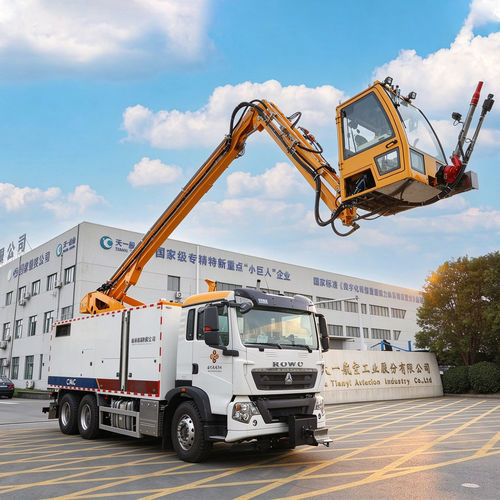
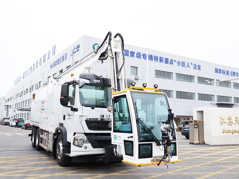
Aircraft de-icing vehicles provide mobile de-icing and anti-icing services for aircraft of all sizes. The transportation and circulation of the de-icing fluid are handled by the same centrifugal pump, which is directly driven by a hydraulic motor. The connection mechanism of this pump motor is installed below the water tank on the right side of the vehicle compartment. The hydraulic motor is directly controlled by the hydraulic pump. When the coil of the electromagnetic valve on the hydraulic pump is energized, the de-icing fluid pump starts to draw water from the water tank and operate. The pressure indication gauge and temperature indication gauge can be used to observe the pressure at the pump outlet and the water temperature. Before the pump is started for the first time or before it is started for the first time after being placed for a long time, the exhaust port on the pump needs to be used for exhaust.
The anti-icing fluid delivery system is a diaphragm pump that is directly driven by a hydraulic motor. The pump motor connection mechanism is installed below the water tank on the left side of the vehicle compartment. The hydraulic motor is controlled by a group of double-acting electromagnetic valves installed on an electromagnetic integrated valve block located below the rotating column. One group of coils is energized, corresponding to one output speed of the anti-icing water pump, which is used for the operation of the anti-icing gun, and is named as the working mode. The other group of coils is energized, corresponding to the self-suction function of the anti-icing water pump, and is named as the self-suction mode. The blower of the anti-icing fluid heater is directly driven by the hydraulic motor. The blower drive device is installed above the inlet of the heater. The hydraulic motor is controlled by two groups of single-acting electromagnetic valves installed on the electromagnetic integrated valve block located below the rotating column. One group of coils is energized, corresponding to the low-speed output of the blower, and both groups of coils are energized, corresponding to the high-speed output of the blower.
The fuel pump of the de-icing fluid heater is directly driven by a hydraulic motor, and the fuel pump drive unit is installed below the side of the heater. The hydraulic motor is controlled by a group of single-acting electromagnetic valves mounted on an electromagnetic integrated valve block installed below the rotating column. When the coil is energized, the fuel pump hydraulic motor outputs the rotational speed. Two filters are installed respectively in the suction and discharge pipelines of the fuel pump to filter the fuel and prevent blockage.